Reverse Engineering STL Files With FreeCAD

If you think about it, STL files are like PDF files. You usually create them using some other program, export them, and then expect them to print. But you rarely do serious editing on a PDF or an STL. But what if you don’t have anything but the STL? [The Savvy Engineer] has a method to help you if you need to reverse engineer an STL file in FreeCAD. Check it out in the video below.

The problem is, of course, that STLs are made up of numerous little triangles. The trick is to switch workbenches and create a shape from mesh. That gets you part of the way.

Once you have a shape, you can convert it to a solid. At that point, you can create a refined copy. This gives you a proper CAD file that you can export to a STEP file. From there, you can use it in FreeCAD or nearly any other CAD package you like to use.

Once you have a proper object, you can easily use it like any other solid body in your CAD program. This is one of those things you won’t need every day, but when you do need it, it’ll come in handy.

Want to up your FreeCAD game? We can help. There are other ways to hack up STL files. You can even import them into TinkerCAD to do simple things, but they still aren’t proper objects.

Continue reading “Reverse Engineering STL Files With FreeCAD”

CAD, From Scratch: MakerCAD

It’s likely that many of you use some form of CAD package, but how many of you have decided you didn’t like the software on offer? [Marcus Wu] did, and instead of griping, he wrote his own CAD software. It’s called MakerCAD, it’s published under an MIT licence, and you can try it yourself.

It’s written in Go, and it’s superficially similar to OpenSCAD in that the interface is through code. The similarity is skin deep though, as it provides the user with constraint solving as described in the video below the break.

As it stands it’s by no means feature complete, but it is now at a point at which it can be evaluated. Simple models can be created and exported as STEP files, so it can be used as a real-world CAD tool.

Whether it will flourish is down to the path it takes and how its community guides it. But we’re pleased to see any new open source projects in this space, which remains overly dominated by proprietary packages. If you try it, write up your experiences, we’d love to see how this develops.

Continue reading “CAD, From Scratch: MakerCAD”

splice-cad assembly

Splice CAD: Cable Harness Design Tool

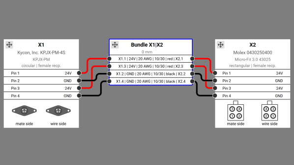
Cable harness design is a critical yet often overlooked aspect of electronics design, just as essential as PCB design. While numerous software options exist for PCB design, cable harness design tools are far less common, making innovative solutions like Splice CAD particularly exciting. We’re excited to share this new tool submitted by Splice CAD.

Splice CAD is a browser-based tool for designing cable assemblies. It allows users to create custom connectors and cables while providing access to a growing library of predefined components. The intuitive node editor enables users to drag and connect connector pins to cable wires and other pinned connectors. Those familiar with wire harnesses know the complexity of capturing all necessary details, so having a tool that consolidates these properties is incredibly powerful.

Among the wire harness tools we’ve featured, Splice CAD stands out as the most feature-rich to date. Users can define custom connectors with minimal details, such as the number of pins, or include comprehensive information like photos and datasheets. Additionally, by entering a manufacturer’s part number, the tool automatically retrieves relevant data from various distributor websites. The cable definition tool is equally robust, enabling users to specify even the most obscure cables.

Once connectors, cables, and connections are defined, users can export their designs in multiple formats, including SVG or PDF for layouts, and CSV for a detailed bill of materials. Designs can also be shared via a read-only link on the Splice CAD website, allowing others to view the harness and its associated details. For those unsure if the tool meets their needs, Splice CAD offers full functionality without requiring an account, though signing in (which is free) is necessary to save or export designs. The tool also includes a version control system, ideal for tracking design changes over time. Explore our other cable harness articles for more tips and tricks on building intricate wire assemblies.

Continue reading “Splice CAD: Cable Harness Design Tool”

Open Source CAD In The Browser

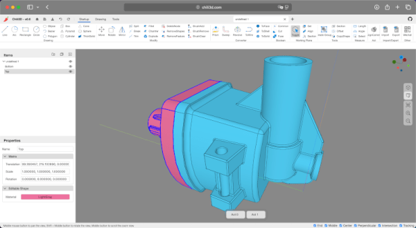
Some people love tools in their browsers. Others hate them. We certainly do like to see just how far people can push the browser and version 0.6 of CHILI3D, a browser-based CAD program, certainly pushes.

If you click the link, you might want to find the top right corner to change the language (although a few messages stubbornly refuse to use English). From there, click New Document and you’ll see an impressive slate of features in the menus and toolbars.

The export button is one of those stubborn features. If you draw something and select export, you’ll see a dialog in Chinese. Translated it has the title: Select and a checkmark for “Determined” and a red X for “Cancelled.” If you select some things in the drawing and click the green checkmark, it will export a brep file. That file format is common with CAD programs, but you’ll need to convert, probably, if you want to 3D print your design.

The project’s GitHub repository shows an impressive slate of features, but also notes that things are changing as this is alpha software. The CAD kernel is a common one brought in via WebAssembly, so there shouldn’t be many simple bugs involving geometry.

We’ve seen a number of browser-based tools that do some kind of CAD. CADmium is a recent entry into the list. Or, stick with OpenSCAD. We sometimes go low-tech for schematics.

Scan Your Caliper For Physical Part Copies

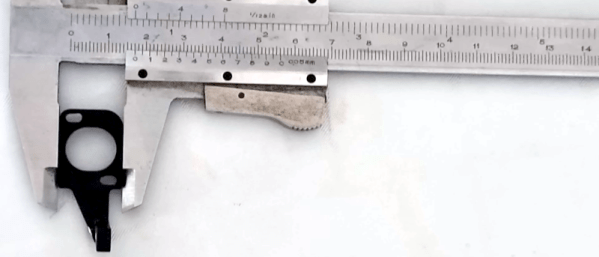
We’ve certainly seen people take a photo of a part, bring it into CAD, and then scale it until some dimension on the screen is the same as a known dimension of the part. We like what [Scale Addition] shows in the video below. In addition to a picture of the part, he also takes a picture of a vernier caliper gripping the part. Now your scale is built into the picture, and you can edit out the caliper later.

He uses SketchUp, but this would work on any software that can import an image. Given the image with the correct scale, it is usually trivial to sketch over the image or even use an automatic tracing function. You still need some measurements, of course. The part in question has a vertical portion that doesn’t show up in a flat photograph. We’ve had good luck using a flatbed scanner before, and there’s no reason you couldn’t scan a part with a caliper for scale.

This is one case where a digital caliper probably isn’t as handy as an old-school one. But it would be possible to do the same trick with any measurement device. You could even take your picture on a grid of known dimensions. This would also allow you to check that the distances at the top and bottom are the same as the distances on the right and left.

Of course, you can get 3D scanners, but they have their own challenges.

Continue reading “Scan Your Caliper For Physical Part Copies”

Belfry OpenSCAD Library (BOSL2) Brings Useful Parts And Tools Aplenty

OpenSCAD has a lot of fans around these parts — if you’re unaware, it’s essentially a code-based way of designing 3D models. Instead of drawing them up in a CAD program, one writes a script that defines the required geometry. All that is made a little easier with the Belfry OpenSCAD Library (BOSL2).

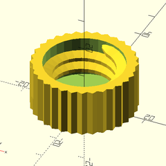
Designing a part like this is a cinch with BOSL2.

BOSL2 has an extensive library of base shapes, advanced functions for manipulating models, and some really nifty tools for creating attachment points on parts and aligning components with one another. If that sounds handy for designing useful objects, you’re in for even more of a treat when you see their functions for gears, hinges, screws, and more.

There’s even one that covers bottle necks and caps. (Those are all standardized by the way, so it’s never been easier to interface to existing bottles or caps in a project.)

OpenSCAD really is very versatile software. It powers useful tools like this screw, washer, and nut generator as well as having more unusual applications like a procedural terrain generator. It’s free, so if you’ve never looked into it, check it out!

Life Without Limits: A Blind Maker’s Take On 3D Printing

In the world of creation, few stories inspire as much as [Mrblindguardian], a 33-year-old who has been blind since the age of two, but refuses to let that hold him back. Using OpenSCAD and a 3D printer, [Mrblindguardian] designs and prints models independently, relying on speech software and touch to bring his ideas to life. His story, published on his website Accessible3D.io, is a call to action for makers to embrace accessibility in their designs and tools.

[Mrblindguardian]’s approach to 3D printing with OpenSCAD is fascinating. Without visual cues, he can still code every detail of his designs, like a tactile emergency plan for his workplace. The challenges are there: navigating software as a blind user, mastering 3D printers, and building from scratch. His tip: start small. Taking on a very simple project allows you to get accustomed to the software while avoiding pressure and frustation.

His successes highlight how persistence, community support, and creativity can break barriers. His journey mirrors efforts by others, like 3D printed braille maps or accessible prosthetics, each turning daily limitations into ingenious innovations. [Mrblindguardian] seems to be out to empower others, so bookmark his page for that what’s yet to come.

Accessible tech isn’t just about empowering. Share your thoughts in the comments if you have similar experiences – or good solutions to limitations like these! As [Mrblindguardian] says on his blog: “take the leap. Let’s turn the impossible into the tangible—one layer at a time”.

Continue reading “Life Without Limits: A Blind Maker’s Take On 3D Printing”