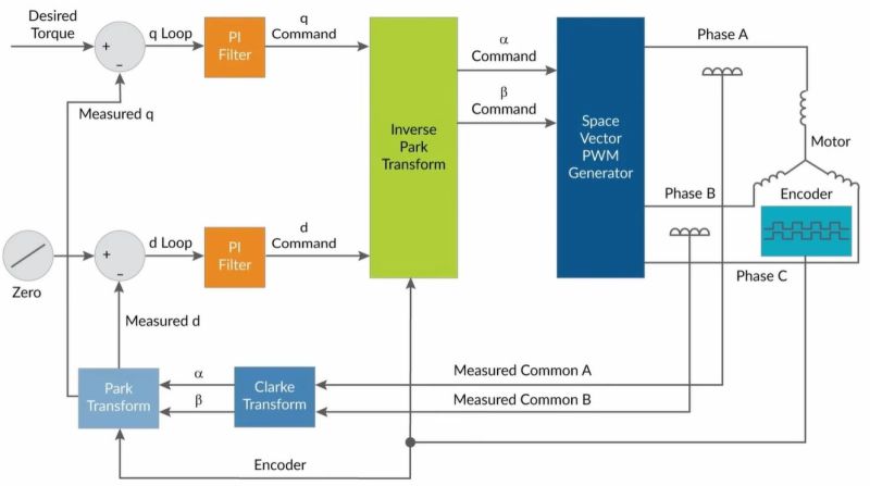
Vector Control, also known as Field Oriented Control or FOC is an AC motor control scheme that enables fine-grained control over a connected motor, through the precise control of its phases. In a recent video [Excessive Overkill] goes through the basics and then the finer details of how FOC works, as well as how to implement it. These controllers generally uses a proportional integral (PI) loop, capable of measuring and integrating the position of the connected motor, thus allowing for precise adjustments of the applied vector.
If this controller looks familiar, it is because we featured it previously in the context of reviving old industrial robotic arms. Whether you are driving the big motors on an industrial robot, or a much smaller permanent magnet AC (PMAC) motor, FOV is very likely the control mechanism that you want to use for the best results. Of note is that most BLDC motors are actually also PMACs with ESC to provide a DC interface.
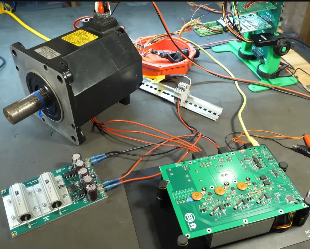
The actual driving is done with two MOSFETs per phase, forming a half-bridge, switching between the two rails to create the requisite PWM signal for each phase. Picking the right type of MOSFET was somewhat hard, especially due to the high switching currents and the high frequency at 25 kHz. The latter was picked to prevent audible noise while driving a robot. Ultimately SiC MOSFETs were picked, specially the GeneSiC G3R30MT12K. Of note here are the four legs, with a fourth Kelvin Source pin added. This is to deal with potential gate drive issues that are explained in the video.
With the hardware in place, whether following the [Excessive Overkill] GitHub projects or not, what makes all of it work is the software. This is where the microcontroller aspect is essential, as it has to do all the heavy lifting of calculating the new optimal vector and thus the current levels per phase. In this controller an STM32F413 is used, which generates the PWM signals to drive the half-bridges, while reading the measurements from the motors with its ADC.
As can be seen in the resulting use of this controller with old industrial robots, the FOC controller works quite well, with quiet and smooth operation. This performance is why we’re likely to see FOC and PMAC motors used in applications like 3D printers in the future, though the rule of ‘good enough’ makes the cost of an FOC controller still a tough upsell over a simple open loop stepper-based system.


Way overcomplicated for tasks where basic microstepping can be done with R-Pi and some Python code. Control engineers are usually creepy and awkward when in presence of a woman.
what a dumb comment
Not at all. The speed and positioning under FOC depends on the error signal derived from the measured motor state, which means you have to accept some error band around the desired path for the control scheme to operate.
This is analogous to the way a stepper motor deviates from the desired position under load, except with a stepper motor you don’t have to compute anything and it’s already built for good precision without active feedback. If the motor is sized incorrectly and cannot perform the required motion with acceptable error, then you can’t help it with FOC because the motor is still too weak or your demands are unrealistic.
The FOC PMAC motor looks good in demos, but you can’t see with the naked eye whether the performance is really superior. What’s likely, you’re spending months of engineering and fine tuning just to arrive at the same point that you’d have with a simple stepper motor. All at the cost of much more complicated control hardware, more software and code, and more things to troubleshoot with the encoders and sensors.
The main deciding question is rather, whether the characteristic torque and power curve of the stepper motor vs. the coarser PMAC motor is better or worse for the application. One control method in itself is not clearly better. Doing FOC for the sake of doing FOC is not a good idea, but nerds are going to nerd about it anyways because it’s complicated and cool.
On the point of torque and power, because the PMAC/BLDC motor is coarser than a stepper motor, it’s going to be a faster motor. For applications where you want direct drive, this is like trying to launch your car in third gear. It can be done, but the performance will suffer until you get up to speed.
For things like 3D printers where you’re constantly slowing down and accelerating from a stop, you will actually spend most of your time going relatively slowly. You’re not extruding at a million miles per hour, and when you are moving rapidly you’re not extruding and not demanding high precision, so the apparent dynamic performance of a BLDC motor is mismatched.
If you gear it down, you face the problem of inertia, because the energy stored in the rotor is proportional to the square of its RPM, so starting and stopping the motor consumes most of your torque.
He does a fairly lengthy discussion of this in the video and describes quite precisely why a FOC is the best option in this application.
Do you have any meaningful input on this, or do you just want to continue talking about other hypothetical scenarios where FOC might not be the best option?
it was nat that part of the comment I was refering to
You confure tree phases motor with stepper motor…
Maybe some MEMS sensors could make FOC a little cheaper in the future?