If there’s anything more frustrating than mounting holes that don’t line up with the thing you’re mounting, we don’t know what it could be. You measure as carefully as possible, you drill the holes, and yet at least one hole ends up being just out of place. Sometimes you can fudge it, but other times you’ve got to start over again. It’s maddening.
Getting solid measurements of the distance between holes would help, which is where these neat snap-on attachments for digital calipers come in. [Chris Long] came up with the 3D printed tools to make this common shop task a little easier, and they look promising. The extensions have cone-shaped tips that align perfectly with the inside edge of the caliper jaws, which lines the jaws up with the center of each hole. You read the center-to-center distance directly off the caliper display, easy peasy.
Of course, there’s also the old machinist’s trick (last item) about zeroing out the calipers after reading the diameter of one of the holes and then measuring the outside-to-outside distance between the two holes. That works great when you’ve got plenty of clearance, but the shorter inside jaws might make measuring something like a populated PCB with this method tricky. For the price of a little filament and some print time, these might be just the tool to get you out of a bind.
Continue reading “3D Printed Caliper Extensions Make Hole Measurement Easier”
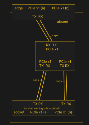 PCIe needs TX pairs connected to RX on another end, like UART – and this is non-negotiable. Connectors will use host-side naming, and vice-versa. As the diagram demonstrates, we connect the socket’s TX to chip’s RX and vice-versa; if we ever get confused, the laptop schematic is there to help us make things clear. To sum up, we only need to flip the names on the link coming to the PCIe switch, since the PCIe switch acts as a device on the card; the two links from the switch go to the E-key socket, and for that socket’s purposes, the PCIe switch acts as a host.