Ok, you caught us. It certainly isn’t going to be the year of Algol. When you think of “old” programming languages, you usually think of FORTRAN and COBOL. You should also think of LISP. But only a few people will come up with Algol. While not a household name, it was highly influential, and now, GCC is on the verge of supporting it just like it supports other languages besides C and C++ these days.
Why bring an old language up to the forefront? We don’t know, but we still find it interesting. We doubt there’s a bunch of Algol code waiting to be ported, but you never know.
I modified a printer a few years ago to handle multiple filaments, but I will admit it was more or less a stunt. It worked, but it felt like you had to draw mystic symbols on the floor of the lab and dance around the printer, chanting incantations for it to go right. But I recently broke down and bought a color printer. No, probably not the one you think, but one that is pretty similar to the other color machines out there.
Of course, it is easy to grab ready-made models in various colors. It is also easy enough to go into a slicer and “paint” colors, but that’s not always desirable. In particular, I like to design in OpenSCAD, and adding a manual intervention step into an otherwise automatic compile process is inconvenient.
The other approach is to create a separate STL file for each filament color you will print with. Obviously, if your printer can only print four colors, then you will have four or fewer STLs. You import them, assign each one a color, and then, if you like, you can save the whole project as a 3MF or other file that knows how to handle the colors. That process is quick and painless, so the question now becomes how to get OpenSCAD to put out multiple STLs, one for each color.
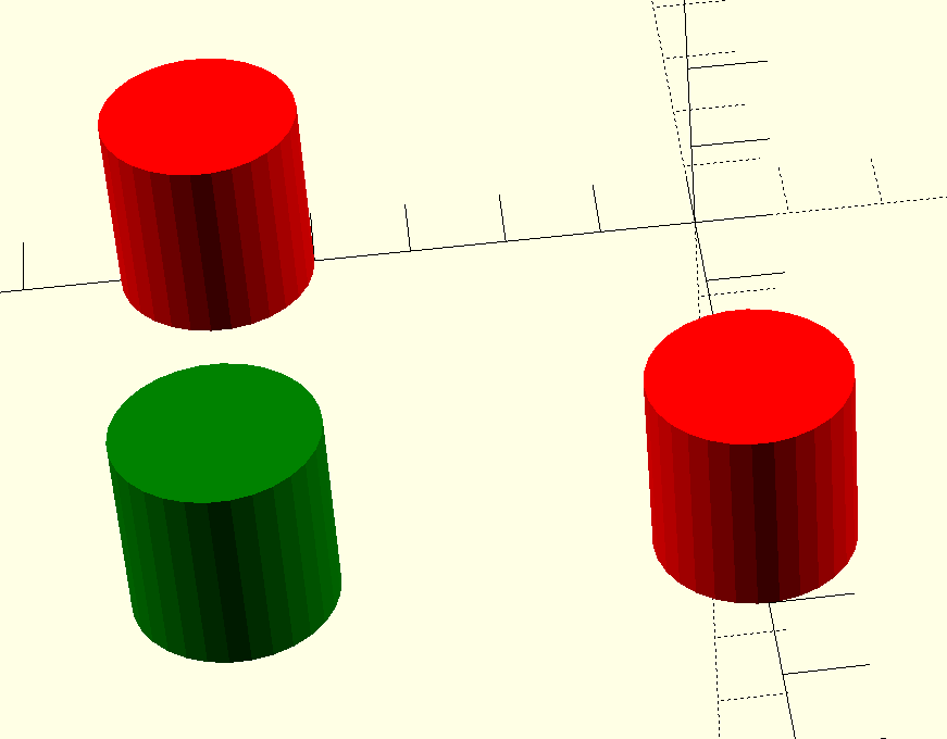
But… color()
OpenSCAD has a color function, but that just shows you colors on the screen, and doesn’t actually do anything to your printed models. You can fill your screen with color, but the STL file you export will be the same. OpenSCAD is also parametric, so it isn’t that hard to just generate several OpenSCAD files for each part of the assembly. But you do have to make sure everything is referenced to the same origin, which can be tricky.
OpenSCAD Development Version Test
It turns out, the development version of OpenSCAD has experimental support for exporting 3MF files, which would allow me to sidestep the four STLs entirely. However, to make it work, you not only have to run the development version, but you also have to enable lazy unions in the preferences. You might try it, but you might also want to wait until the feature is more stable.
Besides, even with the development version, at least as I tried it, every object in the design will still need its color set in the slicer. The OpenSCAD export makes them separate objects, but doesn’t seem to communicate their color in a way that the slicer expects it. If you have a large number of multi-color parts, that will be a problem. It appears that if you do go this way, you might consider only setting the color on the very top-most objects unless things change as the feature gets more robust.
A Better Way
What I really wanted to do is create one OpenSCAD file that shows the colors I am using on the screen. Then, when I’m ready to generate STL files, I should be able to just pick one color for each color I am using.
[CreativeLab] bought a cheap arbitrary waveform generator and noted that it only had a two-pin power cord. That has its ups and downs. We feel certain the intent was to isolate the internal switching power supply to prevent ground loops through the scope probes or the USB connector. However, it is nice to have all your equipment referencing the same ground. [CreativeLab] agrees, so he decided to do something about it.
Opening the box revealed that there was hardly anything inside. The main board was behind the front panel. There was also the power supply and a USB board. Plus lots of empty space. Some argue the case is made too large to be deceptive, but we prefer to think it was to give you a generous front panel to use. Maybe.
It was a simple matter to ground everything to a new three-pin connector, but that left the problem of the USB port. Luckily, since it was already out on its own board, it was easy to wire in an isolator.
Honestly? We’d have hesitated to do this unless we had made absolutely sure it didn’t pose some safety hazard to “jump over” the switching power supply. They are often isolated for some reason. However, the likelihood is that it is just fine. What do you think? Let us know in the comments.
If you built a car in, say, Germany, for use in Canada, you could assume that the roads will be more or less the same. Gravity will work the same. While the weather might not be exactly the same, it won’t be totally different. But imagine designing the Lunar Excursion Module that would land two astronauts on the moon for the first time. No one had any experience landing a craft on any alien body before.
The LEM was amazing for many reasons, but as [Apollo11Space] points out, the legs were a particularly thorny engineering problem. They had to land on mostly unknown terrain, stay upright, allow for the ascent module to take off again, and, of course, not weigh down the tiny spaceship. They also had to survive the blast of the LEM’s engine.
You have some fine pitch soldering to do, but all you have on hand is a big soldering iron. What do you do? There are a few possible answers, but [Mr SolderFix] likes to pull a strand from a large wire, file the point down, and coil it around the soldering iron. This gives you a very tiny hot tip. Sure, the wire won’t last forever, but who cares? When it gives up, you can simply make another one.
Many people have done things like this before — we are guilty — but we really liked [Mr Solder Fix’s] presentation over two videos that you can see below. He coils his wire over a form. In his case, he’s using a screwdriver handle and some tape to get to the right size. We’ve been known to use the shanks of drill bits for that purpose, since it is easy to get different sizes.
If you are sitting on a horde of negatives, waiting for the digital photography fad to die off, it may be time to think about digitizing your old film. [Kinpro1024] can help with the PiDigitzier, an open-source film scanning solution. The build centers around a Pi Zero 2, a Pi HQ camera, and a diffusing LED lighting fixture. Of course, there’s also some miscellaneous hardware and a camera lens; the example used a Pentax 50 mm f1.8 lens.
Half of the project is mechanical. An MDF tower provides a stable 250 mm workspace and decks that can slide up and down using threaded rods and curtain rods. Apparently, leveling the platforms is important not only for the optics but also to allow the MDF to move along the rods without binding.
Every time we check in on [Project326], he’s doing something different with X-rays. This week, he has a passive X-ray imager. On paper, it looks great. No special tube is required and no high voltage needed. Actually, no voltage is needed at all. Of course, there’s no free lunch. What it does take is a long time to produce an image.
While working on the “easy peasy X-ray machine,” dental X-ray film worked well for imaging with a weak X-ray source. He found that the film would also detect exposure to americium 241. So technically, not an X-ray in the strictest sense, but a radioactive image that uses gamma rays to expose the film. But to normal people, a picture of the inside of something is an X-ray even when it isn’t.