LLM Dialogue In Animal Crossing Actually Works Very Well

In the original Animal Crossing from 2001, players are able to interact with a huge cast of quirky characters, all with different interests and personalities. But after you’ve played the game for awhile, the scripted interactions can become a bit monotonous. Seeing an opportunity to improve the experience, [josh] decided to put a Large Language Model (LLM) in charge of these interactions. Now when the player chats with other characters in the game, the dialogue is a lot more engaging, relevant, and sometimes just plain funny.

How does one go about hooking a modern LLM into a 24-year-old game built for an entirely offline console? [josh]’s clever approach required a lot of poking about, and did a good job of leveraging some of the game’s built-in features for a seamless result.

Continue reading “LLM Dialogue In Animal Crossing Actually Works Very Well”

Fully-Local AI Agent Runs On Raspberry Pi, With A Little Patience

[Simone]’s AI assistant, dubbed Max Headbox, is a wakeword-triggered local AI agent capable of following instructions and doing simple tasks. It’s an experiment in many ways, but also a great demonstration not only of what is possible with the kinds of open tools and hardware available to a modern hobbyist, but also a reminder of just how far some of these software tools have come in only a few short years.

Max Headbox is not just a local large language model (LLM) running on Pi hardware; the model is able to make tool calls in a loop, chaining them together to complete tasks. This means the system can break down a spoken instruction (for example, “find the weather report for today and email it to me”) into a series of steps to complete, utilizing software tools as needed throughout the process until the task is finished.

Continue reading “Fully-Local AI Agent Runs On Raspberry Pi, With A Little Patience”

Play Capacitor Cupid With The Matchmaker

Occasionally a design requires capacitors that are much closer to being identical in value to one another than the usual tolerance ranges afford. Precision matching of components from parts on hand might sound like a needle-in-a-haystack problem, but not with [Stephen Woodward]’s Capacitor Matchmaker design.

The larger the output voltage, the greater the mismatch between capacitors A and B.

The Matchmaker is a small circuit intended to be attached to a DVM, with the output voltage indicating whether two capacitors (A and B) are precisely matched in value. If they are not equal, the voltage output indicates the degree of the mismatch as well as which is the larger of the two.

The core of the design is complementary excitation of the two capacitors (the CD4013B dual flip-flop achieves this) which results in a measurable signal if the two capacitors are different; nominally 50 mV per % of mismatch. Output polarity indicates which of the capacitors is the larger one. In the case of the two capacitors being equal, the charges cancel out.

Can’t precision-matched capacitors be purchased? Absolutely, but doing so is not always an option. As [Stephen] points out, selection of such components is limited and they come at an added cost. If one’s design requires extra-tight tolerances, requires capacitor values or types not easily available as precision pairs, or one’s budget simply doesn’t allow for the added cost, then the DIY approach makes a lot more sense.

If you’re going to go down this road, [Stephen] shares an extra time-saving tip: use insulated gloves to handle the capacitors being tested. Heating up a capacitor before testing it — even just from one’s fingers — can have a measurable effect.

[Stephen]’s got a knack for insightful electronic applications. Check out his PWMPot, a simple DIY circuit that can be an awfully good stand-in for a digital potentiometer.

A Closer Look Inside A Robot’s Typewriter-Inspired Mouth

[Ancient] has a video showing off a fascinating piece of work: a lip-syncing robot whose animated electro-mechanical mouth works like an IBM Selectric typewriter. The mouth rapidly flips between different phonetic positions, creating the appearance of moving lips and mouth. This rapid and high-precision movement is the product of a carefully-planned and executed build. When we featured this project before, we wanted to see under the hood. Now we can.

Behind the face is a ball that, when moving quickly enough, gives the impression of animated mouth and lips. The new video gives a closer look at how it works.

[Ancient] dubs the concept Selectramatronics, because its action is reminiscent of the IBM Selectric typewriter. Instead of each key having a letter on a long arm that would swing up and stamp an ink ribbon, the Selectric used a roughly spherical unit – called a typeball – with letters sticking out of it like a spiky ball.

Hitting the ‘A’ key would rapidly turn the typeball so that the ‘A’ faced forward, then satisfyingly smack it into the ink ribbon at great speed. Here’s a look at how that system worked, by way of designing DIY typeballs from scratch. In this robot, the same concept is used to rapidly flip a ball bristling with lip positions.

We first saw this unusual and fascinating design when its creator showed videos of the end result on social media, pronouncing it complete. We’re delighted to see that there’s now an in-depth look at the internals in the form of a new video (the first link in this post, also embedded below just under the page break.)

The new video is wonderfully wordless, preferring to show rather than tell. It goes all the way from introducing the basic concept to showing off the final product, lip-syncing to audio from an embedded Raspberry Pi.

Continue reading “A Closer Look Inside A Robot’s Typewriter-Inspired Mouth”

Send Images To Your Terminal With Rich Pixels

[darrenburns]’ Rich Pixels is a library for sending colorful images to a terminal. Give it an image, and it’ll dump it to your terminal in full color. While it also supports ASCII art, the cool part is how it makes it so easy to display an arbitrary image — a pixel-art rendition of it, anyway — in a terminal window.

How it does this is by cleverly representing two lines of pixels in the source image with a single terminal row of characters. Each vertical pixel pair is represented by a single Unicode ▄ (U+2584 “lower half block”) character. The trick is to set the background color of the half-block to the upper pixel’s RGB value, and the foreground color of the half-block to the lower pixel’s RGB. By doing this, a single half block character represents two vertically-stacked pixels. The only gotcha is that Rich Pixels doesn’t resize the source image; if one’s source image is 600 pixels wide, one’s terminal is going to receive 600 U+2584 characters per line to render the Rich Pixels version.

[Simon WIllison] took things a step further and made show_image.py, which works the same except it resizes the source image to fit one’s terminal first. This makes it much more flexible and intuitive.

The code is here on [Simon]’s tools GitHub, a repository for software tools he finds useful, like the Incomplete JSON Pretty Printer.

Design Scanimations In A Snap With The Right Math

Barrier-grid animations (also called scanimations) are a thing most people would recognize on sight, even if they didn’t know what they were called. Move a set of opaque strips over a pattern, and watch as different slices of that image are alternately hidden and revealed, resulting in a simple animation. The tricky part is designing the whole thing — but researchers at MIT designed FabObscura as a design tool capable not only of creating the patterned sheets, but doing so in a way that allows for complex designs.

The barrier grid need not consist of simple straight lines, and movement of the grid can just as easily be a rotation instead of a slide. The system simply takes in the desired frames, a mathematical function describing how the display should behave, and creates the necessary design automatically.

The paper (PDF) has more details, and while it is possible to make highly complex animations with this system, the more frames and the more complex the design, the more prominent the barrier grid and therefore the harder it is to see what’s going on. Still, there are some very nice results, such as the example in the image up top, which shows a coaster that can represent three different drink orders.

We recommend checking out the video (embedded below) which shows off other possibilities like a clock that looks like a hamster wheel, complete with running rodent. It’s reminiscent of this incredibly clever clock that uses a Moiré pattern (a kind of interference pattern between two elements) to reveal numerals as time passes.

We couldn’t find any online demo or repository for FabObscura, but if you know of one, please share it in the comments.

Continue reading “Design Scanimations In A Snap With The Right Math”

Reverse-Engineering Mystery TV Equipment: The Micro-Scan

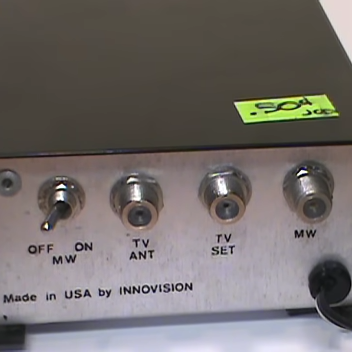
[VWestlife] ended up with an obscure piece of 80s satellite TV technology, shown above. The Micro-Scan is a fairly plan metal box with a single “Tune” knob on the front. At the back is a power switch and connectors for TV Antenna, TV Set, and “MW” (probably meaning microwave). There’s no other data. What was this, and what was it for?

Satellite TV worked by having a dish receive microwave signals, but televisions could not use those signals directly. A downconverter was needed to turn the signal into something an indoor receiver box (to which the television was attached) could use, allowing the user to select a channel to feed into the TV.

At first, [VWestlife] suspected the Micro-Scan was a form of simple downconverter, but that turned out to not be the case. Testing showed that the box didn’t modify signals at all. Opening it up revealed the Micro-Scan acts as a combination switchbox and variable power supply, sending a regulated 12-16 V (depending on knob position) out the “MW” connector.

So what is it for, and what does that “Tune” knob do? When powered off, the Micro-Scan connected the TV (plugged into the “TV Set” connector) to its normal external antenna (connected to “TV Antenna”) and the TV worked like a normal television. When powered on, the TV would instead be connected to the “MW” connector, probably to a remote downconverter. In addition, the Micro-Scan supplied a voltage (the 12-16 V) on that connector, which was probably a control voltage responsible for tuning the downconverter. The resulting signal was passed unmodified to the TV.

It can be a challenge to investigate vintage equipment modern TV no longer needs, especially hardware that doesn’t fit the usual way things were done, and lacks documentation. If you’d like to see a walkthrough and some hands-on with the Micro-Scan, check out the video (embedded bel0w).

Continue reading “Reverse-Engineering Mystery TV Equipment: The Micro-Scan”