2025 Component Abuse Challenge: Conductive Filament Makes A Meltable Fuse

Everything is a fuse if you run enough current through it. Or at least [JohnsonFarms.us] seems to think so, which has led him to design 3D-printed fuses made from conductive PLA filament.

Conductive filament is a meltable resistor, which, if one squints hard enough, is basically a fuse.

In theory a 3D printed fuse works the same as a normal one: excessive current draw will cause the conductive plastic to briefly become a heater, causing it to self-destruct and break the electrical connection. There’s a risk of melted plastic and perhaps a nonzero combustion risk, but [JohnsonFarms.us] is less interested in whether this is a good idea and more interested in whether it can work at all, and with what degree of predictability and/or regret.

His experiments so far show that printed fuses are essentially meltable resistors with values between 300 Ω and 1250 Ω, depending on shape. What it takes to bring those to roughly 60 °C, where PLA softens, and around 150 °C, where PLA melts, is next on the to-do list.

Whatever conclusions are reached, it is interesting to think of conductive filament as a meltable resistor, and ponder what unusual applications that might allow.

Most conductive filaments have high resistance, but not all. Some, like Electrifi by Multi3D, have extremely low resistance and were used in a project that made 3d-printed logic gates.

A hand holding the circuit in its active state

2025 Component Abuse Challenge: A Self-Charging LED Flasher By Burkhard Kainka

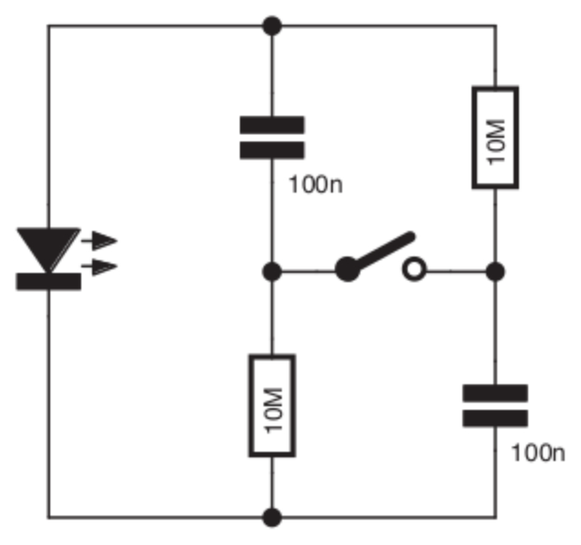
[Tito] entered a Self-Charging LED Flasher into the Component Abuse Challenge. It’s a simple re-build of a design by the unstoppable [Burkhard Kainka], and while [Tito] doesn’t explain its workings in detail, it’s a clever experiment in minimalism, and a bit of a head-scratcher at the same time.

You press a button and an LED flashes.  But there is no battery, so how does it work? Maybe the schematic to the right here will help. Or does it confound? Look at it yourself before reading on and see if you can figure out how it works.

Continue reading “2025 Component Abuse Challenge: A Self-Charging LED Flasher By Burkhard Kainka”

2025 Component Abuse Challenge: Boosting Voltage With Just A Wire

Switching power supplies are familiar to Hackaday readers, whether they have a fairly conventional transformer, are a buck, a boost, or a flyback design. There’s nearly always an inductor involved, whose rapid change in magnetic flux is harnessed to do voltage magic. [Craig D] has made a switching voltage booster that doesn’t use an inductor, instead it’s using a length of conductor, and no, it’s not using the inductance of that conductor as a store of magnetic flux.

Instead it’s making clever use of reflected short pulses in a transmission line for its operation. Electronics students learn all about this in an experiment in which they fire pulses down a length of coax cable and observe their reflections on an oscilloscope, and his circuit is very similar but with careful selection of pulse timing. The idea is that instead of reflected pulses canceling out, they arrive back at the start of the conductor just in time to meet a pulse transition. This causes them to add rather than subtract, and the resulting higher voltage pulse sets off down the conductor again to repeat the process. We can understand the description, but this is evidently one to sit down at the bench and experiment with to fully get to grips with.

Continue reading “2025 Component Abuse Challenge: Boosting Voltage With Just A Wire”

2025 Component Abuse Challenge: An LED As A Light Dependent Capacitor

The function of an LED is to emit light when the device is forward biased within its operating range, and it’s known by most people that an LED can also operate as a photodiode. Perhaps some readers are also aware that a reverse biased LED also has a significant capacitance, to the extent that they can be used in some RF circuits in the place of a varicap diode. But how do those two unintentional properties of an LED collide? As it turns out, an LED can also behave as a light dependent capacitor. [Bornach] has done just that, and created a light dependent sawtooth oscillator.

The idea is simple enough, there is a capacitance between the two sides of the depletion zone in a reverse biased diode, and since an LED is designed such that its junction is exposed to the external light, any photons which hit it will change the charge on the junction. Since the size of the depletion zone and thus the capacitance is dependent on the voltage and thus the charge, incoming light can thus change the capacitance.

The circuit is a straightforward enough sawtooth oscillator using an op-amp with a diode in its feedback loop, but where we might expect to find a capacitor to ground on the input, we find our reverse biased LED. The video below the break shows it in operation, and it certainly works. There’s an interesting point here in that and LED in this mode is suggested as an alternative to a cadmium sulphide LDR, and it’s certainly quicker responding. We feel duty bound to remind readers that using the LED as a photodiode instead is likely to be a bit simpler.

This project is part of the Hackaday Component Abuse Challenge, in which competitors take humble parts and push them into applications they were never intended for. You still have time to submit your own work, so give it a go!

Continue reading “2025 Component Abuse Challenge: An LED As A Light Dependent Capacitor”

2025 Component Abuse Challenge: Making A TTL Demultiplexer Sweat

When we think of a motor controller it’s usual to imagine power electronics, and a consequent dent in the wallet when it’s time to order the parts. But that doesn’t always have to be the case, as it turns out that there are many ways to control a motor. [Bram] did it with a surprising part, a 74ACT139 dual 4-line demultiplexer.

A motor controller is little more than a set of switches between the supply rails and the motor terminals, and thus how it performs depends on a few factors such as how fast it can be switched, how much current it can pass, and how susceptible it is to any back EMF or other electrical junk produced by the motor.

In this particular application the motor was a tiny component in a BEAM robot, so the unexpected TTL motor controller could handle it. The original hack was done a few decades ago and it appears to have become a popular hack in the BEAM community.

This project is part of the Hackaday Component Abuse Challenge, in which competitors take humble parts and push them into applications they were never intended for. You still have time to submit your own work, so give it a go!

2025 Component Abuse Challenge: The Sweet Sound Of A Choking Transformer

The Component Abuse Challenge is dragging all sorts of old, half-forgotten hacks out of the woodwork, but this has got to be the most vintage: [KenS] started using a transformer as a variable choke on his speakers 55 years ago.

The hack is pretty bone-dead simple. A choke is an inductor in an audio (or any other) circuit designed to, well, choke off higher-than-desired frequencies. We featured a deep dive a few years back if you’re interested. An inductor is a coil of wire, usually (but not necessarily) wound around a core of iron or ferrite. A transformer? Well, that’s also a coil of wire around a core… plus an extra coil of wire. So when [KenS], back in his salad days, had a tweeter that a was a little too tweety, and no proper choke, he grabbed a transformer instead.

This is where inspiration hit: sure, if you leave the second winding open, the transformer acts like a standard choke. What happens if you short that second winding? Well, you dampen the response of the first winding, and it stops choking, to the point that it acts more like a straight wire. What happens if you don’t short the second winding, but don’t leave it wide open? [KenS] stuck a potentiometer on there, and found it made a handy-dandy variable choke with which to perfectly tune the tone response of his speakers. Changing the resistance changes the rate at which high frequencies are choked off, allowing [KenS] to get the perfect frequency response with which to rock out to Simon & Garfunkel, The Carpenters and The Guess Who. (According to the Billboard Top 100 for 1970, those are who you’d be listening to if you had conventional tastes.)

While we can’t say the transformer is really being tortured in this unusual mode, it’s certainly not how it was designed, so would qualify for the “Junk Box Substitutions” category of the Component Abuse Challenge. If you’ve made similar substitutions you’d like to share, don’t wait another 55 years to write them up– the contest closes November 11th.

Transformer image: Hannes Grobe, CC BY-SA 4.0.

2025 Component Abuse Challenge: Load Cell Anemometer

When you think anemometer, you probably don’t think “load cell” — but (statistically speaking) you probably don’t live in Hurricane Country, which is hard on wind-speed-measuring-whirligigs. When [BLANCHARD Jordan] got tired of replacing professionally-made meteorological eggbeaters, he decided he needed something without moving parts. Whatever he came up with would probably qualify for the Component Abuse Challenge, but the choice of load cells of all things to measure wind speed? Yeah, that’s not what the manufacturer intended them for.

In retrospect, it’s actually a fairly obvious solution: take a plate of known area, and you’re going to get a specific force at a given air speed. The math isn’t hard, it’s just not how we normally see this particular measurement done. Of course, a single plate would have to be pivoted to face the wind for an accurate reading, which means moving parts– something specifically excluded from the design brief. [Jordan] instead uses a pair of load cells, mounted 90 degrees to one another, for his anemometer. One measures the force in a north-south axis, and the other east-west, allowing him to easily calculate both wind speed and direction. In theory, that is. Unfortunately, he vibe coded the math with ChatGPT, and it looks like it doesn’t track direction all that well. The vibe code runs on an ESP32 is responsible for polling data, tossing outliers, and zeroing out the load cells on the regular.

Continue reading “2025 Component Abuse Challenge: Load Cell Anemometer”